Bar Phantoms
Four-quadrant Bar Phantoms
Four-quadrant Bar Phantoms

Simplifies and speeds the acquisition set-up time and increases the reproducibility of the QC measurements.
Key features include mounting and set-up that allow the Specphan™ phantom itself to be scanned off the table in the air, eliminating the table attenuation issue and enabling the user to position the detector(s) as close to the phantom as needed. This mount design simplifies and speeds the acquisition set-up time and increases the reproducibility of the QC measurements.
The mounting procedure is simple. The Specphan™ phantom case is placed on the patient table and is secured by wrapping the case’s velcro strap around the table. An extension piece is fitted onto the case and the phantom is then affixed to this extension thus suspending it in air between the detector(s). The phantom is quickly leveled by turning an adjustment knob on the extension piece.
The design of the Specphan™ phantom was developed in response to a number of performance standard groups’ test proposals, including: (1) the American Association of Physicists in Medicine (AAPM) “Quantitation of SPECT performance: Report of Task Group 4,
Nuclear Medicine Committee”
(2) the National Electrical Manufacturers Association (NEMA) “Nuclear Medicine Section Recommendations for implementing SPECT instrumentation quality control.
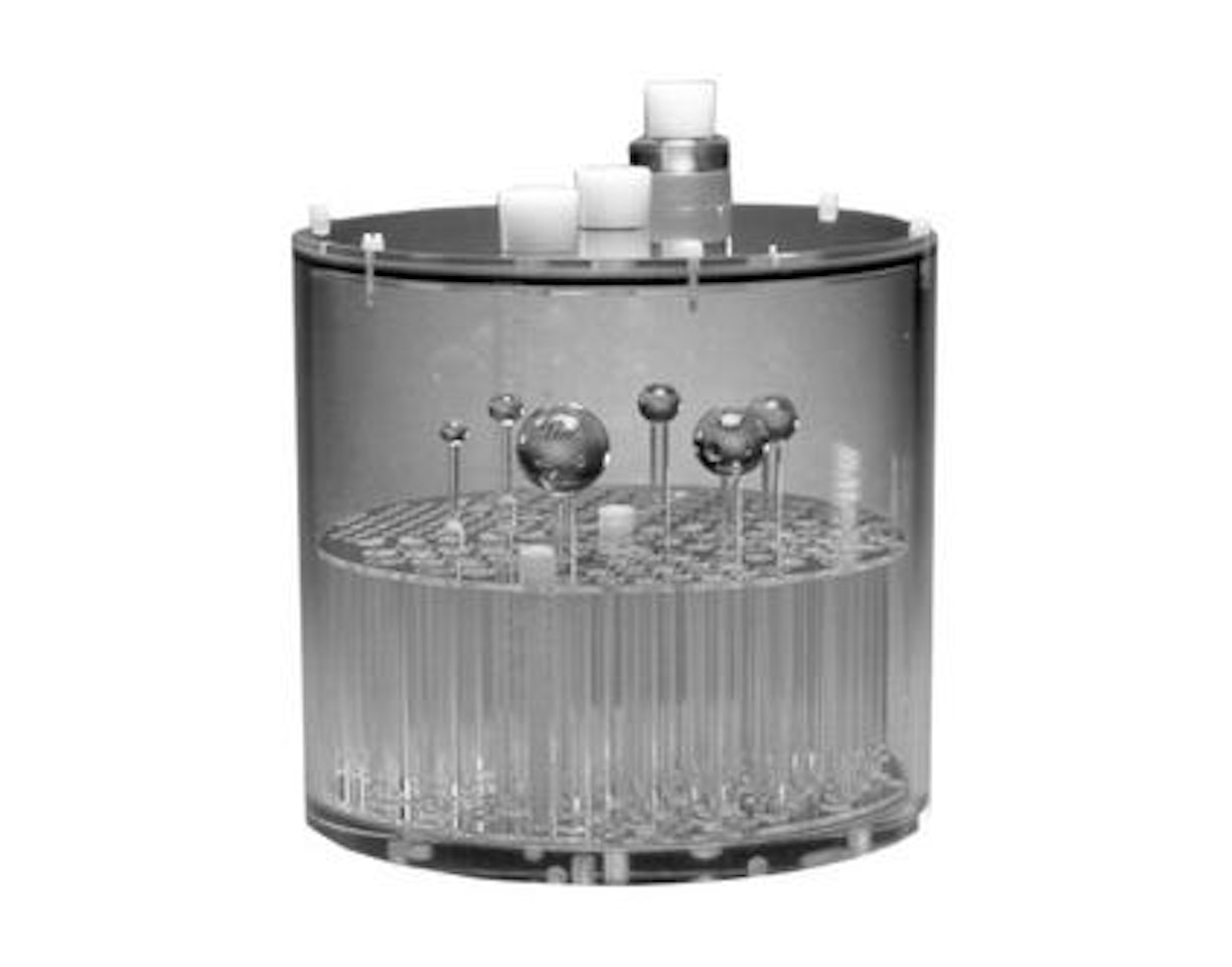
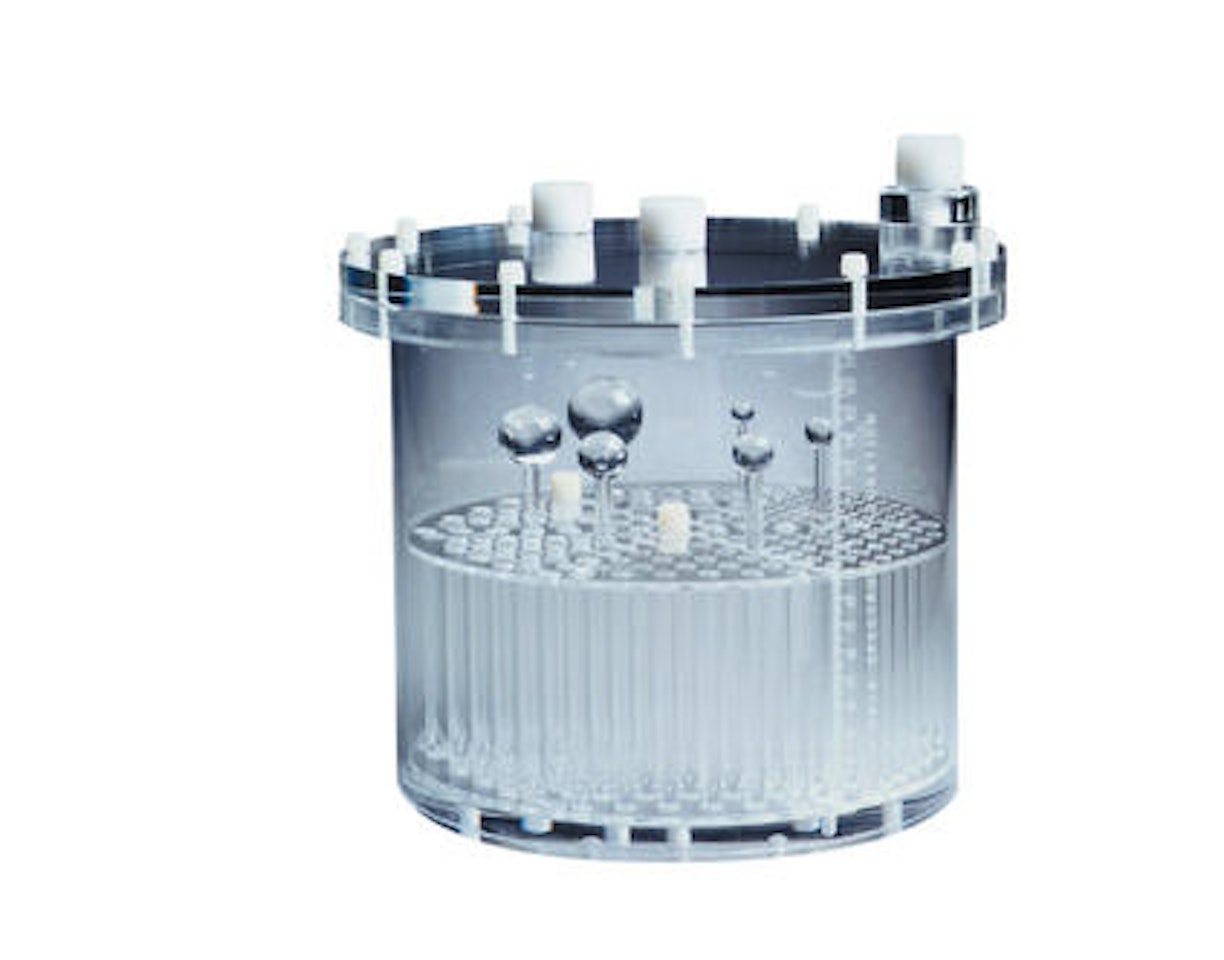
This section provides options to incorporate a point source, which is mounted on the fill plug positioned at the center or at radial plug locations. This source contains a well (3mm diameter x 5mm length) that can be mounted outside or inside the Specphan™ housing. Spatial resolution is measured by calculating the full-width at half-maximum (FWHM), or full-width tenth-maximum (FWTM) measurements of the point spread function (PSF) along the vertical and horizontal axes in the axial plane.
When positioned in the radial fill port, the point source holder can be used to calibrate the center of rotation when the point source data is evaluated in the x-axis. Similarly, detector tilt can be determined when the point source data is evaluated in the horizontal axis of the sagittal plane or the vertical axis of the coronal plane.
Slice width is a reconstruction parameter that defines the thickness or the number of slices that are summed to generate a reconstructed image. Methodology for this measurement resembles that for CT, whereby the full-width at half-maximum (FWHM) of the background corrected, angled ramp profile is computed for each ramp using linear interpolation. In the Specphan™, a channel 20 mm x 10 mm thick at 23o is used as a hot target, providing a magnification factor of 2.3 times for slice width measurement. A trigonometric conversion is then performed, based on the known angle of the ramps, to yield the slice width in millimeters. This measurement indicates the extent of volume averaging, and can be used to optimize the slice widths used for specific clinical acquisition and processing protocol. Since these ramps are always used in opposing pairs, a phantom offset (z-axis) can also be used to evaluate scan localizer’s accuracy or external patient alignment systems.
This pixel test section is used to verify the image pixel size and evaluate the degree of non-linearity or geometric distortion. To validate the pixel size, the phantom uses four hot calibration holes that are 5mm in diameter and separated by 120mm (169mm apart in the orthogonal direction). Based on the known physical locations of these holes, the pixel dimensions can be calculated for the x and y axes.
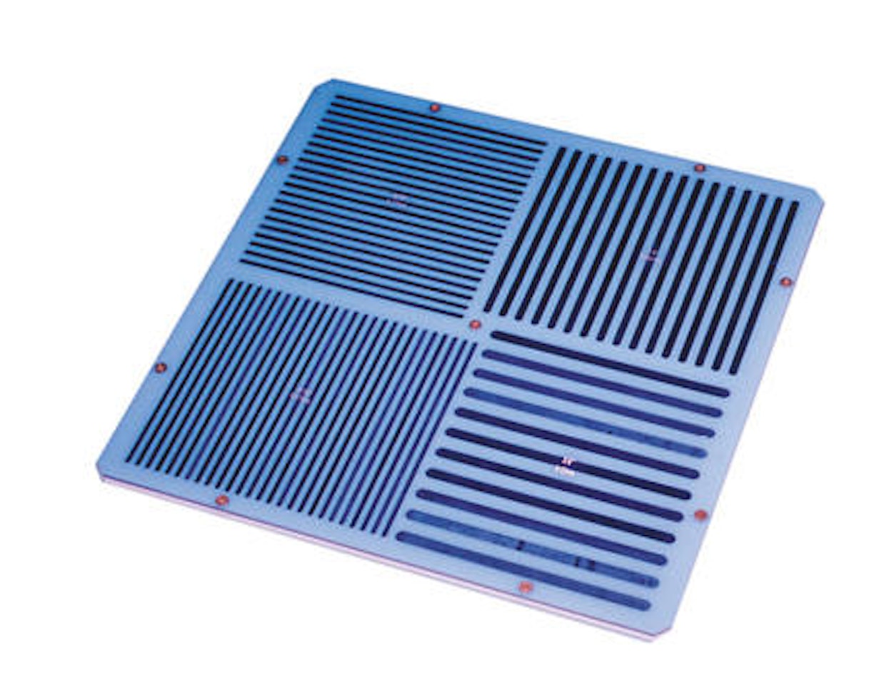
This slice width/pixel size section contains ‘hot’ and ‘cold’ resolution gauges (2mm, 4mm, 6mm, and 8mm) for visual evaluation of spatial resolution. The correspondence to square wave pattern is 2.5 lp/cm, 1.25 lp/cm, 0.83 lp/cm and 0.625 lp/cm respectively.
This section, approximately 14cm in length and 20cm in diameter, can be used to evaluate the image parameters for noise (percentage of root mean square), artifacts, image uniformity, and slice and volume sensitivity.
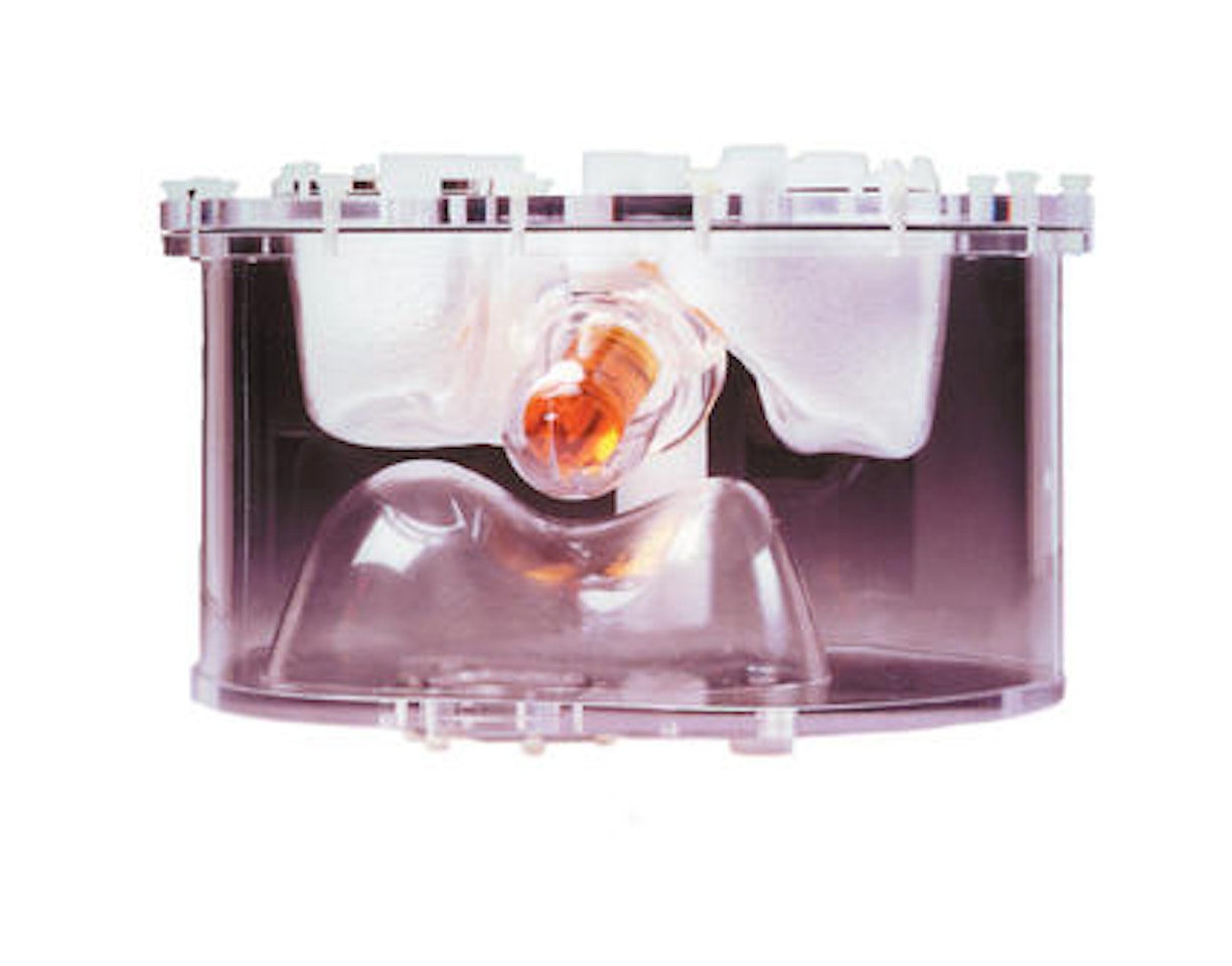
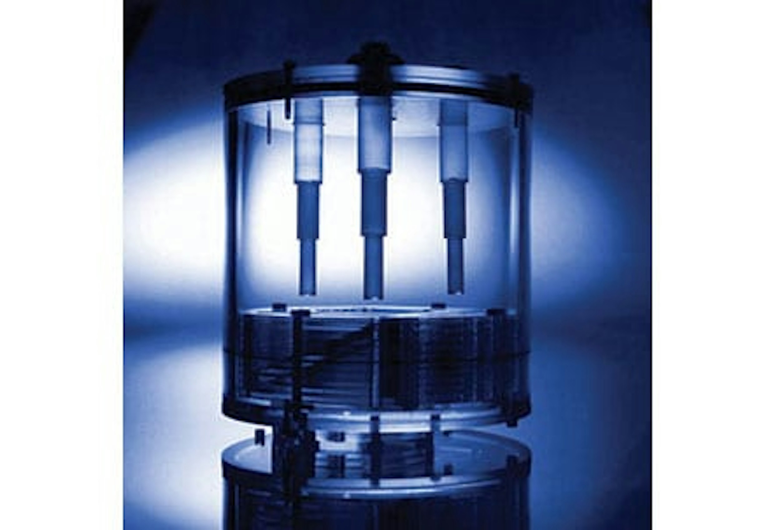
Three low contrast inserts are threaded into the end of the Specphan™ housing. The three inserts can be placed in a radial pattern 63.5mm off the center axis or one can be placed in the phantom’s central axis. The inserts are comprised of three sections, 10, 15 and 20mm in diameter and 40mm long. The inserts are filled through a port at the threaded end. The inserts can be used to simulate ‘hot’ or ‘cold’ lesions.
| 5230-0132 | Spect & PET Phantom |
Do you have a question or need a custom solution? We're here to help guide your research.
Looking for Services or Support?
We're here to help.